Page 35 - BPW axles with air suspension Series O SL AL
P. 35

Installation guidelines           7.1
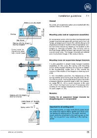

                                                              G Geenneerraall
                               Bolted on at ride height
                                                              As a rule, air suspension axles are installed with the
                                                              vehicle frame on its back.
                                                       Ride height


              Welding                                         M Moouunnttiinngg  aaxxlleess  aanndd  aaiirr  ssuussppeennssiioonn  aasssseemmbblliieess


                                                              Air suspension axles with mounted trailing arms and
                      Hub flange
                                                              hanger brackets are generally picked up at the hub
                 Aligning with the kingpin /                  flange, arranged according to the vehicle design and
                 steering turnplate                           aligned accurately in relation to the longitudinal cen-
                                                              tre line of the vehicle by means of the middle of the
                                                              kingpin or steering turnplate. The centring aid on
               Conical holder for                             the hub flange differs between lightweight hubs and
               conventional wheel                             conventional hubs. The hanger brackets are welded
               hubs (closed flange)
                                                              onto the bottom flange of the vehicle frame.


                                                              M Moouunnttiinngg  lloooossee  aaiirr  ssuussppeennssiioonn  hhaannggeerr  bbrraacckkeettss

                                                              It is also possible to attach loose, hanger brackets
                                                              separately. In  this case, the spring bolt mounting
                                                              points of the hanger brackets are aligned in relation
                                                              to the longitudinal centre  line of the vehicle by
                                                              means of the middle of the kingpin or steering turn-
                                                              plate.
                                                              In this installation position, the tolerances of the
                                                              spring centres and trailing arm lengths must be ta-
                                                              ken into account. The hanger bracket position in the
                                                              sideways direction must be kept within the toleran-
                                                              ce range FM (0, +2) to  avoid stresses in the axle
                                                              unit. Check the track and correct if necessary after
                                                              welding on the hanger brackets or mounting the ax-
                        Welding                               les (see pages 44, 45).


                                                              R Reemmaarrkkss::
             Aligning with the kingpin /
             steering turnplate                               H Heeaattiinngg   tthhee   aaiirr   ssuussppeennssiioonn   hhaannggeerr   bbrraacckkeettss   ffoorr
                                                              s sttrraaiigghhtteenniinngg  wwoorrkk  iiss  nnoott  ppeerrmmiitttteedd
                           DIRECTION OF TRAVEL

                                          +2
                          Spring centre FM 0                  I Immppoorrttaanntt  ffoorr  aallll  wweellddiinngg  wwoorrkk!!
                                                              The trailing arms, air bags and plastic pipes must
                                                              be protected against flying sparks and weld spat-
                                                              ter during all welding work. The earth terminal
                                                              must never be attached to the trailing arm or the
                                                              hub. Do not perform any welding on the trailing
                                                              arms!


           BPW-EA-Luft 1023701e                                                                            35
   30   31   32   33   34   35   36   37   38   39   40