Page 42 - BPW axles with air suspension Series O SL AL
P. 42

BPW axles with air suspension


          8          Shock absorber


                                                               G Geenneerraall
                                                               The purpose of shock absorbers is to rapidly redu-
                                                               ce the vibrations occurring between the axle and
                                                               body during driving. This  prevents any further
                                                               yawing of the body and running gear components,
                                                               and ensures  that the tyres  maintain optimum
                                                               ground contact. In turn,  this ground contact is
                                                               responsible for the tracking stability and braking
                                                               properties of the vehicle.


                                                               B BPPWW  ssttaannddaarrdd  sshhoocckk  aabbssoorrbbeerr
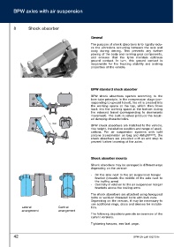
                                                               BPW shock absorbers operate according  to  the
                                                               twin-tube principle. In the compression stage (cor-
                                                               responding to upward travel), the oil is pressed into
                                                               the working space at the top, which then flows
                                                               back into the working space at the bottom during
                                                               the rebound travel (corresponding to downwards
                                                               movement). The built-in valves produce the requir-
                                                               ed damping characteristics.
                                   L max.
                                                               BPW shock absorbers are matched to the vehicle,
                                                               ride height, installation position and range of appli-
                                                               cations. For air suspension systems with split
                                                               pistons (combination air bag and Airlight Direct ), the
                                                               shock absorbers are provided with an end stop to
                                                               prevent further lowering of the axles.


                                                               S Shhoocckk  aabbssoorrbbeerr  mmoouunnttss

                                                               Shock absorbers may be arranged in different ways
                                                               depending on the version:

                                                               -   On the side next to the air suspension hanger
                                                                  bracket (towards the middle of the axle next to
                                                                  the trailing arms)
                                                               -  Centrally in relation to the air suspension hanger
                                                                  brackets above the trailing arms
                                                               The shock absorbers are attached using hexagonal
                                                               bolts or weld-on threaded bolts with lock nuts.
                                                               Depending on the version, it may be necessary to
                                                               use additional rings, discs and sleeves for installa-
                Lateral                  Central               tion.
                arrangement              arrangement
                                                               The following depictions provide an overview of the
                                                               current versions.

                                                               Tightening torques, see last page.


          42                                                                                BPW-EA-Luft 1023701e
   37   38   39   40   41   42   43   44   45   46   47