
Page 48 - BPW axles with air suspension Series O SL AL
P. 48
BPW axles with air suspension
9.3 Track correction at air suspension axles with adjustable hanger bracket
G Geenneerraall
It is necessary to check the tracking accuracy dur-
ing installation as well as after repairs on axles,
brackets or trailing arms.
If a track correction is necessary, it can be carried
out as follows:
The diagonal measurements must be checked as
described on page 46.
R Reemmaarrkkss::
The spring U-bolts must not be undone in the case
of air suspension axles with adjustable hanger
brackets.
M Mooddiiffiieedd sspprriinngg bboolltt mmoouunnttiinngg iinn aallll T Trraacckk ccoorrrreeccttiioonn
A Aiirrlliigghhtt IIII aaiirr ssuussppeennssiioonn uunniittss ffrroomm
b buuiilldd yyeeaarr 99//22000077 oonnwwaarrd dss!! 1. Raise and support the vehicle frame
From the September 2007 build year onwards, all 2. Exhaust the air out of the air bags
Airlight II air suspension units will be provided 3. Slacken the lock nuts on the spring pivot bolt
with a modified spring bolt mounting. The former
functional principle of the mounting with integrat- 4. Align the centre axle (reference axle)
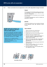
ed track adjustment is maintained in this case. 5. Slide the connecting linkage on both sides, as
The following components are modified: required, upwards or downwards with light
hammer blows (see fig.)
- Spring bolt and nut (M 30 to M 24)
- Welded bushes in the hanger bracket (for Ø 24) 6. Make sure the inner and outer connecting link-
- Wear discs (for Ø 24) ages on each hanger bracket are adjusted
symmetrically!
- Connecting link discs (for Ø 24)
- Disc (for Ø 24) 7. Tighten lock nut on the spring pivot bolt to the
specified torque
8. Check the track settings of the front and rear
axles and re-align if necessary
9. Remove supports from underneath the vehicle
and inflate the air bags
5
5
Connecting link disc
48 BPW-EA-Luft 1023701e