
Page 22 - KNORR Pneumatic Disc Brake
P. 22
5
Functional and Visual Check
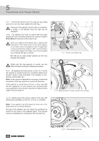
5.2.7. Pull off the adjuster cap (37) using the tag, taking
care not to lose the shear adapter (61) (see Fig.).
Removal of the adjuster cap (37) with a screwdriver,
or similar, is not allowed since the seal may be
damaged.
5.2.8. The adjuster (23) must be turned with the shear
adapter (61) anti-clockwise (viewed from actuator side) for
three clicks (increasing running clearance).
Never turn adjuster (23) without shear adapter (61) 37 23
being fitted. If the shear torque of the shear adapter
is exceeded, then it is designed to fail. Try again with 61
a new (unused) shear adapter. With a second failure
of the shear adapter the caliper must be exchanged
since internal damage is present. 5.2.7 - Remove cap using the tag
Do not use an open-ended spanner as this may
damage the adapter.
Make sure the ring spanner or socket can turn
freely clockwise during the following procedure.
5.2.9 By applying the brake (about 2 bar) 5 to 10 times
the spanner or socket should turn clockwise (viewed from
actuator side) in small increments if the adapter is func-
tioning correctly (see Fig.).
Note: As the number of applications increases, incremental
movement of the ring-spanner or socket will decrease.
If the spanner or socket does not turn or turns only with
the first application or turns forward and backward with 61
every application, the automatic adjuster has failed and the
caliper must be replaced. 5.2.9 - Apply the brake 5-10 times, spanner turns clockwise
5.2.10. Lightly grease the contact surface of the cap with
white grease (available as Part No. II14525 or II32868).
Note: A new adjuster cap (37) should be fitted even if the 37
brake pads are not being replaced.
The tag of the adjuster cap (37) should be positioned as
shown by the arrow in the adjacent figure. This ensures
access is maintained for subsequent removal (see Fig.).
5.2.10 - Tag positioning of the cap
22