
Page 29 - BPW axles with air suspension Series O SL AL
P. 29
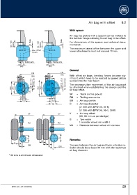
Air bag with offset          6.2


                                                              W Wiitthh  ssppaacceerr

                                                              Air bag top plates with a spacer can be welded to
                                                              the bottom flange allowing the air bag to be offset.
           60 / 100  Spacer  5 Plate  60 / 100  Spacer  5 Plate  For dimensions of the spacer, see technical docu-
                                                              mentation.
                                                              The maximum lateral offset between the upper and
                  BPW 30     max. offset   BPW 36             lower attachments must not exceed 10 mm.
                             10 mm


                      Trailing arm             Trailing arm
                   V                        V
                   (60)                    (80)
                                                              G Geenneerraall
                            FM                        FM
                                           80         BM
                   60       BM                                With offset air bags, bending forces become sig-
                                           200
                  140                                         nificant which have to be reacted by gusset plates
                                                              welded into the main beam.
                   M12      M 22 x 1.5  Air connection  M12  M 22 x 1.5  Air connection  The necessary free movement of the air bag must
           300  240  120  150      360  300  120  210         be checked when establishing the design and the
                          25                                  air bag offset.
                                                    25
                                                              SP    =  Track on the ground
                     5
                                               5              FM    =  Trailing arm centre
                     53
                     73                       75              BM    =  Air bag centre
                                              95              D     =  Air bag diameter
                                                                      (∅ 300 with BPW 30, 30 K)
                                                                      (∅ 360 with BPW 36, 36-1, 36 K)
                         SP                        SP         V     =  Air bag offset
                                                                      (60; 80 mm as per design )
                                                              B     =  Tyre width
                                                                      ( consider wheel rim width )
                         FM                        FM
                                                              MA    =  Distance between wheel rim centres


                                                      D
                          D                                   R Reemmaarrkkss::
                                     MA
             B                           B
                 *
                 30      BM                *                  The gap between the air bag and tyres or brake cy-
                                           30       BM
                    V                                         linder should be at least 30 mm with the maximum
                                               V
                                                              air bag diameter.
         * 30 mm is minimum dimension


           BPW-EA-Luft 1023701e                                                                            29