Page 24 - BPW axles with air suspension Series O SL AL
P. 24

BPW axles with air suspension


          4.5.6      Struts / bolted steel air suspension hanger brackets

          Example of struts in bolted steel air                G Geenneerraall
          suspension hanger brackets.
                                                               With the new, bolted Airlight II air suspension han-
                                                               ger bracket, BPW is offering the opportunity of pre-
                                                               fabricating compact vehicle frames without air
                        1b
                                                               suspension hanger brackets, coating them and not
                                                               assembling them to the complete axle unit until the
                                                               final assembly stage. The actual configuration is
                                                               only defined when it comes to mounting the
                                                               suspension units. The bolted system therefore offers
                                                               the vehicle manufacturer logistical advantages and
                                                               increases flexibility in production.


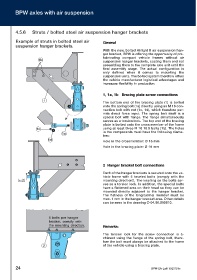
                                                               1 1,,  11aa,,  11bb BBrraacciinngg  ppllaattee  ssccrreeww  ccoonnnneeccttiioonnss
                           1
                                                               The bottom end of the bracing plate (1) is bolted
                                                               onto the spring bolt (1a) directly using an M 18 con-
                                                               nection bolt with nut (1c, 1d), which therefore per-
                                                               mits direct force  input. The spring bolt itself is a
                                                               special bolt with flange. The flange simultaneously
                                                               serves as a torsion lock. The top end of the bracing
                                                               plate is bolted onto the cross member of the frame
                       1c                                      using at least three M 16 10.9 bolts (1b). The holes
                                                               in the components must have the following diame-
                                       1a
                                                               ters:
                              1d
                                                               Hole in the crossmember: Ø 16 mm
                                                               Hole in the bracing plate: Ø 18 mm


                                                               2 2    HHaannggeerr  bbrraacckkeett  bboolltt  ccoonnnneeccttiioonnss
                                                               Each of the hanger brackets is secured onto the ve-
                                                               hicle frame with 5 knurled bolts (comply with the
               1                                               mounting direction!). The knurling on the bolts ser-
                                                               ves as a torsion lock. In addition, the special bolts
                                                               have a flattened area on their head so they can be
                                                               mounted directly adjacent to the hanger bracket.
                                                               The flatness of the longitudinal member must be
                                                               max. 1 mm in the hanger bracket area. Other details
                                                               can be seen in the drawing C-04.00.509610.


                               5 bolts per hanger
                               bracket, comply with
                               the mounting direction.         R Reemmaarrkkss::


                                                               The torsion lock for the screw connection is a-
                                                               chieved using the flange of the spring bolt, there-
                                                               fore the bolt must always be attached to the frame
                           2                                   of the vehicle using a bracing plate.


          24                                                                                BPW-EA-Luft 1023701e
   19   20   21   22   23   24   25   26   27   28   29