
Page 28 - KNORR Pneumatic Disc Brake
P. 28
6
Brake Pad Replacement
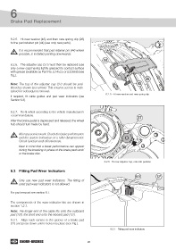
6.2.5. Fit new washer (45) and then new spring clip (26)
to the pad retainer pin (44) (use only new parts).
It is recommended that pad retainer pin (44) where
possible, is installed pointing downwards.
44
6.2.6. The adjuster cap (37) must then be replaced (use
only a new cap) having lightly greased its contact surface
with grease (available as Part No. II14525 or II32868) (see
Fig.).
26
Note: The tag of the adjuster cap (37) should be posi- 45
tioned as shown (see arrow). This ensures access is main-
tained for subsequent removal.
6.2.5 - Fit new washer and new spring clip
If required, fit cable guides and pad wear indicators (see
Section 6.3).
6.2.7. Re-fit wheel according to the vehicle manufacturer’s
recommendations.
37
After the brake pedal is depressed and released, the wheel
hub should turn freely by hand.
After any service work: Check the brake performance
and the system behaviour on a roller dynamometer.
Check function and effectiveness.
Bear in mind that a lower performance can appear
during the breaking-in phase of the brake pads and/
or the brake disc.
6.2.6 - Fit new adjuster cap, note tab position
6.3 Fitting Pad Wear Indicators
101 12 2
Only use new pad wear indicators. The fitting of
used pad wear indicators is not allowed.
For pad removal see section 6.1.
The components of the wear indicator kits are shown in
section 1.2.1.
Note: The longer end of the cable fits onto the outboard
pad (12 ), the short end onto the inboard pad (12 ).
2
1
6.3.1. Align each sensor in the groove of a brake pad
(12) and press down until it locks into place (see Fig.).
6.3.1 - Fitting pad wear indicators
28