Page 30 - KNORR Pneumatic Disc Brake
P. 30

6


        Brake Pad Replacement


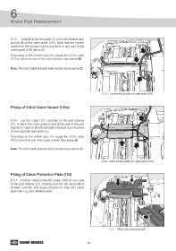
        6.3.5.  Carefully insert the cable (101) into the retainer tabs
        (arrows A) of the cable guide (105). Note that the shorter
        cable from the inboard pad is not fixed to any part of the                             B
        cable guide (105) (arrow C).
                                                                        105           101
        Depending on the vehicle type, the supply line of the cable                         A
        (101) is fixed into one of the outer retainer clips (arrow B).

        Note: The short cable (inboard side) remains loose (arrow C).


                                                                                            C


                                                                      6.3.5 - Cable fixture position on cable guide (105)


        Fitting of Cable Guide Variant (105a)

                                                                                             B
                                                                                  101
                                                                    105a                 11
        6.3.6.  Lay the cable (101) centrally on the pad retainer
        (11). Position the cable guide (105a) at the side of the pad
        retainer (11) (arrow D) and with light pressure clip into place
        on the opposite side (see Fig.).
        Depending on the vehicle type, the supply line of the cable
        (101) is fixed into one of the outer retainer clips (arrow B).


        Note: The short cable (inboard side) remains loose (arrow C).              D      C


                                                                      6.3.6 - Cable fixture position on cable guide (105a)


        Fitting of Cable Protection Plate (104)
                                                                                          E
        6.3.7.  Position cable protection plate (104) on one side
        of the pad retainer (11), making sure the tab (arrow E) is
        located correctly, and apply pressure to snap into place                                     104
        (see main Fig. and detailed view).


                                                                               11


                                                                                                E


                                                                           6.3.7 - Fitting cable protection plate


                                                            30
   25   26   27   28   29   30   31   32   33   34   35