
Page 39 - KNORR Pneumatic Disc Brake
P. 39
8
Caliper Replacement
8.2 Fitting Caliper to Carrier -
(Carrier assembled on vehicle)
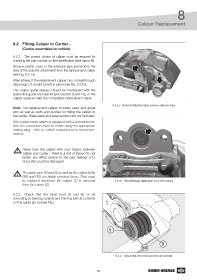
8.2.1. The correct choice of caliper must be ensured by
checking the part number on the identification label (arrow X).
Remove plastic cover or the adhesive tape (arrow Y) in the Y
area of the actuator attachment from the replacement caliper
(see Fig. 8.2.1a). X
Alternatively, if the replacement caliper has a breakthrough
diaphragm, it should be left in place (see Fig. 8.2.1b).
The caliper guide sleeves should be overhauled with the
respective guide and seal kit (see Section 9 and 10), or the
caliper replaced with the compatible rationalised caliper.
8.2.1a - Note identification label, remove adhesive tape
Note: The replacement caliper includes seals and guide
pins as well as bolts and bushes for fitting the caliper to
the carrier. Brake pads and wear sensors are not included.
If the replacement caliper is equipped with a potentiometer,
then the connection must be made using the appropriate
mating plug - refer to vehicle manufacturer’s recommen-
dations.
Never hold the caliper with your fingers between
caliper and carrier - there is a risk of injury! Do not
fasten any lifting device to the pad retainer (11),
since this could be damaged.
The guide pins (4) and (5) as well as the caliper bolts
(39) and (40) are highly stressed items. They must
be replaced whenever the caliper (1) is removed 8.2.1b - Breakthrough diaphragm to be left in place
from the carrier (2).
8.2.2. Check that the inner boot (9 and 9c or 9d
according to bearing variant) and the ring (58) sit correctly
on the guide pin (5) (see Fig.).
5
9
58
8.2.2 - Check that inner boot and ring sit correctly
39