
Page 43 - KNORR Pneumatic Disc Brake
P. 43
9
Inner Boot (9) Replacement
9 Inner Boot (9) Replacement
For ease of reference, each component of a tool is referred (C)
to by an identification number e.g. (T28); a complete tool
(containing one or more such components) has been given
a letter code e.g. (E) - see section 2.1.
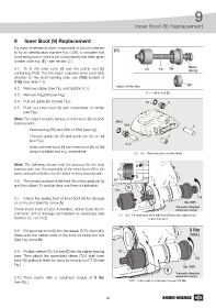
9.1. To fit the inner boot (9) use the pull-in tool (C) T07 T10 T08 Washer
DIN 125
containing (T08). For the black coloured inner boot (9d),
situated on the short bearing side, use (T06) instead of
(T08) (see table 2.1). T06*
9.2. Remove caliper (see Fig. and Section 8.1). *Replaces T08 when fitting
9.3. Remove ring (58) (see Fig.). 9.1 - Pull-in tool (C)
9.4. Pull out guide pin (5) (see Fig.). 58 9
9.5. Push out inner boot (9) with screwdriver or similar
(see Fig.).
Note: For caliper variants having an inner boot (9) on both
bearing sides: 58c/d 9c/d
- Remove ring (58) and (58c or 58d) (see Fig.). 5
- Remove guide pin (5) and guide pin (4c or 4d) 6
(see Fig.).
4c /d
- Ease out inner boot (9) and inner boot (9c or 9d)
using a suitable tool e.g. screwdriver.
9.2 - 9.5 - Remove parts as described
Note: The following shows only the process for the long A
bearing side, but the assembly of the inner boot (9) is the
same principle whether for the short or long bearing side.
B
9.6. The contact surface of the boot (9) on the guide pin (5) T07
and the caliper (1) must be clean and free of lubrication. 9
T07
9.7. Check the sealing face of inner boot (9) for damage T10
or corrosion (see Fig. arrow A). T08 (T06*)
Check brass bush (7) and, if installed, rubber bush (6), for *Only used for fitting black
coloured inner boot (9d)
corrosion, dirt or damage and replace as necessary (see 9.7 - 9.9 - Fit new inner boot with tool (C) into the caliper bore,
Section 10.1 or 10.2) pull-in by hand
9.8. Fit new inner boot (9) into the sleeve (T07) of tool (C). 8 Nm
Make sure the rubber folds of the boot sit inside the tool (max.)
(See Fig. arrow B).
9.9. Position sleeve (T07) of tool (C) into the caliper bearing T07
bore. Then attach the assembled sleeve (T07) (with inner
boot (9)) pulling-in firstly by hand by turning tool (T10) (see T10
Fig.). T08 (T06*)
9
*Only used for fitting black
9.10. Then, pull-in with a maximum torque of 8 Nm coloured inner boot (9d)
(see Fig.). 9.10 - Pull-in with a maximum torque of 8 Nm
43