
Page 41 - KNORR Pneumatic Disc Brake
P. 41
8
Caliper Replacement
The inner boot (9) must be in a compressed
condition otherwise the caliper´s freedom of
movement will be limited. 10
H
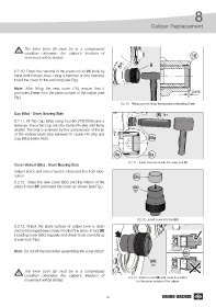
8.2.10. Press the mandrel of the press-in tool (H) firstly by
hand until it stops, then, using a hammer on the mandrel,
insert the cover to the end stop (see Fig.).
Note: After fitting the new cover (10), ensure that it
protrudes 2 mm from the plane surface of the caliper (see 2 mm
Fig.).
8.2.10 - Fitting cover to stop, final position protruding 2 mm
Cap (68a) - Short Bearing Side (K) T11
8.2.11. Fit the Cap (68a) using tool (K) (Z003934) and a
Hammer. Force the Cap into the Guide Pin (4a) until firmly
seated. The seal is achieved by the compression of the lip
of the Rubber Bush (6a) between th Guide Pin (4a) and
Cap (68a) (siehe Abb). 68a
4a 6a
8.2.11 - Insert Cap into Guide Pin using tool (K)
Cover Variant (68c) - Short Bearing Side
Caliper bores and cover must be clean and free from lubri-
cation. 68c
8.2.12. Clean the new cover (68c) and the interior of the
press-in tool (M) and insert the cover as shown (see Fig.). (M)
T27
8.2.12 - Insert cover into tool (M)
8.2.13. Check the plane surface of caliper bore is clean
and not damaged (see arrow). Position the press-in tool (M)
including cover (68c) squarely and check it sits correctly as
shown (see Fig.).
Note: Do not tilt the tool when assembling the cover (68c)!
68c
(M)
T27
The inner boot (9) must be in a compressed
condition otherwise the caliper´s freedom of 8.2.13 - Press-in tool (M) with cover in position
movement will be limited. on the plane surface of the caliper
41