Page 59 - BPW axles with air suspension Series O SL AL
P. 59

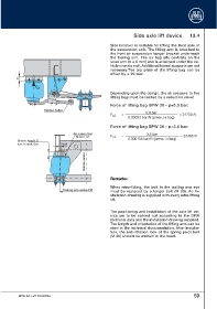
Side axle lift device          13.4

                                                              Side location is suitable for lifting the front axle of
                                                              the suspension unit. The lifting arm is attached to
                                                              the front air suspension hanger bracket underneath
                                                              the trailing arm. The air bag sits centrally on the
                                                              lever arm (V = 0 mm) and is attached under the ve-
                                                              hicle chassis trail. Additional lateral supports are not
                                                              necessary.The top plate of the lifting bag can be
                                                              offset by ± 20 mm.
           U

                    F LB
                                                              Depending upon the design, the air pressure to the
                                                              lifting bag must be limited by a reduction valve!
                                                              Force of lifting bag BPW 30 - p=5.0 bar:
                         Rubber buffer
                                                                                 5.0 bar
                                                              F LB  =                                                        = 21750 N
                                                                       0.00023 bar/N (press. in bag)

                                                              Force of lifting bag BPW 36 - p=3.5 bar:
                                         Air connection                          3.5 bar
                                           M 22 x 1.5         F LB  =                                                         = 22450 N
           Spacer height U                                             0.000156 bar/N (press. in bag)
                                   +
           acc. to tech. doc.     V20
                                                Vehicle centre


                                                              R Reemmaarrkkss::

                                                              When retro-fitting, the bolt in the trailing arm eye
                                   Trailing arm centre FM
                                                              must be replaced by a longer bolt (M 30). An in-
                                                              stallation drawing is supplied with every retro-fitting
                                                              kit.


                                                              The positioning and installation of the axle lift de-
                                                              vice are  to  be carried out according to the BPW
                                                              technical data and the installation drawing supplied.
                                                              The length and orientation of the lifting arm can be
                                                              seen in the technical documentation. After installa-
                                                              tion, the anti-rotation lock of the spring pivot bolt
                                                              (M 30) should be welded to the head.


           BPW-EA-Luft 1023701e                                                                            59
   54   55   56   57   58   59   60   61   62   63   64