
Page 60 - BPW axles with air suspension Series O SL AL
P. 60
BPW axles with air suspension
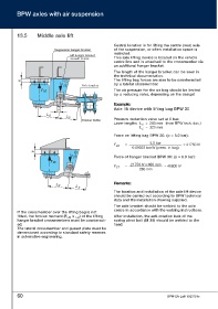
13.5 Middle axle lift
Central location is for lifting the centre (rear) axle
Suspension hanger bracket of the suspension, or when installation space is
restricted.
Lift hanger bracket
on axle centre This axle lifting device is located on the vehicle
centre line and is attached to the crossmember via
an additional hanger bracket.
The length of the hanger bracket can be seen in
the technical documentation.
U The lifting bag forces are also to be counteracted
by a lateral crossmember.
F ST Axle bracket
F LB The air pressure for the air bag should be limited
by a reducing valve, depending on the design!
E Exxaammppllee::
Axle lift device with lifting bag BPW 30
Y
L Z
L X
Pressure reduction valve set at 5 bar.
Rubber buffer
Lever lengths L X = 280 mm (from BPW tech. doc.)
L Z = 320 mm
Force on lifting bag BPW 30: (p = 5.0 bar):
5.0 bar
F LB = = 21750 N
0.00023 bar/N (press. in bag)
U
Force of hanger bracket BPW 30: (p = 5.0 bar):
F ST
F LB
21750 Nx 600 mm
F ST = = 46600 N
280 mm
R Reemmaarrkkss::
L Z
L X
The location and installation of the axle lift device
should be carried out according to BPW technical
data and the installation drawing supplied.
The axle bracket should be welded to the axle
centre in accordance with the welding instructions.
If the crossmember over the lifting bag is not
fitted, the torsion moment (F LB x ) of the lifting After installation, the anti-rotation lock of the
LZ
hanger bracket crossmembers must be counteract- spring pivot bolt (M 30) should be welded to the
ed. head.
The lateral crossmember and gusset plate must be
dimensioned according to standard safety reserves
in automotive engineering.
60 BPW-EA-Luft 1023701e