
Page 45 - KNORR Pneumatic Disc Brake
P. 45
10
Guide Pin Bush/Sleeve Replacement
10 Guide Pin Bush/Bearing Variants
Replacement
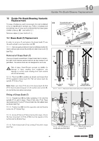
(D) Tool combination to pull-in and
For ease of reference, each component of a tool is referred groove the brass bush (7)
to by an identification number e.g. (T28); a complete tool
(containing one or more such components) has been given Washer
a letter code e.g. (E) - see section 2.1. T14 DIN 125
T08 T12
Remove caliper (1) (see Section 8.1).
T13
T16
10.1 Brass Bush (7) Replacement T14
In order to remove, fit and groove the brass bush (7) use Tool combination to
the pull-out/pull-in and grooving tool (D). pull-out the brass bush (7)
10.1.1. Remove guide pin (5) and inner boot (9) (see Section 9). 10 - Tool combination (D)
Clean surfaces (see arrows A and B) and clean brass bush (7) D
(see Fig.).
Removal of Brass Bush (7) T12
The use of impact screwdrivers / impact wrenches in conjunc-
tion with Knorr-Bremse service tools for air disc brakes is not A
permitted. The service tools are not designed for such use.
Risk of injury. Knorr-Bremse accepts no liability for 7
damage or injury resulting from negligence, any
damage to service tools resulting from such actions
will void all warranty.
10.1.2. Place tool (D) in position as shown and ensure that
(T14) is guided in brass bush (7). Pull out brass bush via T13
spindle (T13) (see Fig.). T14 B
Brass Bush (7) Brass Bush (7) Tool combination
Note: Make sure that (T14) sits in the brass bush (7).Tool installed removed incorrectly positioned!
(T12) must be placed square on the surface (see arrow A). 10.1.1 - 10.1.2 - Removal of brass bush using tool combination (D)
Do not tilt the tool when removing!
T13
Fitting of Brass Bush (7)
10.1.3. Prepare tool (D) by firstly screwing (T14) onto the T14
spindle (T13) until it stops. Place (T08) onto (T13). Place T08 T14
new brass bush (7) onto (T16) and insert into the caliper bore A
as shown (see Fig.).
10.1.4. Position tool (D) from the opposite end and loosely
screw into (T16) (see Fig.).
7
10.1.5. Screw (T13) into (T16) by hand until it stops. Check 7
the free movement of (T16); (T08) must lie square on the T16 T16
surface (arrow A) (see Fig.).
10.1.6. Pull-in brass bush (7) by turning (T14) until it stops
(see Fig.). 10.1.3 - 10.1.5 Positioning of 10.1.6 - Pull-in brass bush by
tool (D) with new brass bush turning (T14)
45