
Page 51 - KNORR Pneumatic Disc Brake
P. 51
10
Guide Pin Bush/Sleeve Replacement
Fitting of Rubber Bush (6d)
10.2.29. Clean the area around the bearing.
10.2.30. Place rubber bush (6d) onto (T06) (which T10
replaces (T08) of tool (C)).
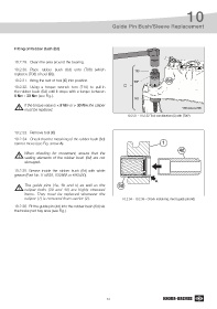
10.2.31. Bring the rest of tool (C) into position. T06* 6d
10.2.32. Using a torque wrench turn (T10) to pull-in C
the rubber bush (6d) until it stops with a torque between
8 Nm - 30 Nm (see Fig.).
T07
If the torque value is < 8 Nm or > 30 Nm the caliper
must be replaced. *(T06) replaces (T08)
10.2.31 - 10.2.32 Tool combination (C) with (T06*)
10.2.33. Remove tool (C)
10.2.34. Check that the metal ring of the rubber bush (6d)
cannot move (see Fig. arrow A). 1
4d
When checking for movement, ensure that the
sealing elements of the rubber bush (6d) are not
damaged.
10.2.35. Grease inside the rubber bush (6d) with white
grease (Part No. Il14525, II32868 or K93430).
A
The guide pins (4a, 4b and 5) as well as the 6d
caliper bolts (39 and 40) are highly stressed
items. They must be replaced whenever the
caliper (1) is removed from carrier (2). 10.2.34 - 10.2.36 - Check metal ring, insert guide pin (4d)
10.2.36. Fit the guide pin (4d) into the rubber bush (6d) via
the brake pad bay area (see Fig.).
51