
Page 49 - KNORR Pneumatic Disc Brake
P. 49
10
Guide Pin Bush/Sleeve Replacement
Fitting of Bearing Variants (6)
T18
Fitting of Rubber Bush (6a) or (6b) T19
10.2.14. Check bore for corrosion and clean.
10.2.15. Wind out the grub screw (from (T19)) on the tool
(R) so it cannot contact the caliper surface (see Fig. insert). 6ab
Grub screw
10.2.16. Push rubber bush (6a) or (6b) into (T18) of tool (R) DIN 915
(see Fig.).
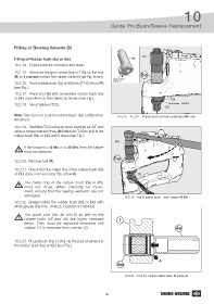
10.2.17. Place tool (R) with assembled rubber bush (6a)
or (6b) in position on the caliper as shown (see Fig.). T19
10.2.18. Hand tighten (T22). Grub screw DIN 915
T22
Note: Take care not to tilt the rubber bush (6a) or (6b) when 10.2.16 - 10.2.18 - Rubber bush and tool combination (R) in situ
winding in.
10.2.19. Stabilise (T22) using an open spanner 24 A/F and
using a torque wrench (max. 45 Nm) turn (T20) to pull-in the
rubber bush (6a) or (6b) until it stops (see Fig.).
T20
If the torque is < 8 Nm or > 45 Nm, then the caliper
must be replaced.
6ab
10.2.20. Remove tool (R).
10.2.21. Check that the metal ring of the rubber bush (6a)
or (6b) does not move (see Fig. arrow A). T22
The metal ring of the rubber bush (6a) or (6b)
must not move. When checking for move-
ment, ensure that the sealing elements are not
damaged. 10.2.19 - Pull-in rubber bush - max. torque 45 Nm
10.2.22. Grease inside the rubber bush (6a) or (6b) with
white grease (Part No. Il14525, II32868 or K93430).
The guide pins (4a, 4b and 5) as well as the
caliper bolts (39 and 40) are highly stressed 1
items. They must be replaced whenever the
caliper (1) is removed from carrier (2). 4ab
10.2.23. Fit guide pin (4a) or (4b) via the pad abutment in
the rubber bush (6a) or (6b) (see Fig.).
A
6ab
10.2.21 - 10.2.23 -Check rubber bush, fit guide pin
49