
Page 50 - KNORR Pneumatic Disc Brake
P. 50
10
Guide Pin Bush/Sleeve Replacement
Fitting of Guide Sleeve (6c)
The guide sleeve (6c) must be positioned so that its
tab and the groove in the caliper bore are aligned.
Note: Caliper groove can be on the left or right side of the
caliper bore.
10.2.24. Place (T14) onto the aligned guide sleeve (6c)
and lightly tap with a hammer to make sure it is seated T14
correctly in the caliper bore (see Fig.).
10.2.25. Complete the positioning of tool (N) through the 6c
caliper bore and guide sleeve (6c) (see Fig.).
10.2.26. Hand tighten spindle (T20).
10.2.27. Stabilise spindle (T20) using a ring spanner on 10.2.24 - Guide sleeve (6c) lightly tapped in position
(T14) and by using a torque wrench (max. 18 Nm) turn the
spindle (T20) to pull-in the guide sleeve (6c) until it stops
(see Fig.).
If the torque value is < 4 Nm or > 18 Nm, the caliper T14
must be replaced.
Do not turn (T14) as this may cause the guide sleeve
(6c) to turn and lose its alignment with the groove in 6c
the caliper bore.
N
T08
Remove all assembly tools. T06
T05
T20
10.2.25 - 10.2.27 tool combination (N) in position
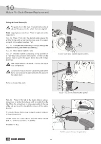
10.2.28. Press in the tab of the Guide Sleeve using a
screwdriver or similar tool whose width is smaller than the
tab. Place the screwdriver as close as possible to the top
of the tab and bend the tab into the groove of the caliper 6c
(see fig.)
The Guide Sleeve (6c) is now secured against rotational
and axial movement.
Grease inside the Guide Sleeve (6c) with white Grease
(Part No. Il14525, II32868 or K093430).
Fit Guide Pin (4c).
10.2.28 - press in the tab of the guide sleeve
50